EMPOWR Dual Mobility™


EMPOWR Dual Mobility™
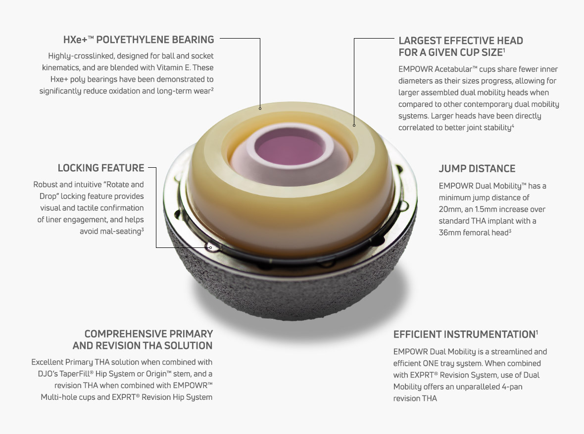
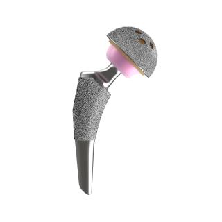
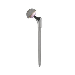
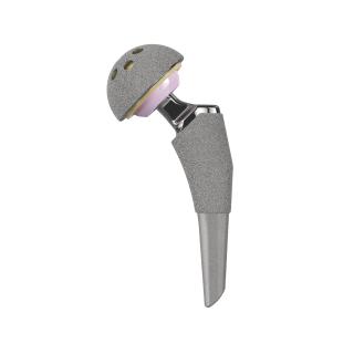
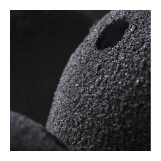
EMPOWR Dual Mobility™ is engineered for enhanced joint stability and helps reduce risks of dislocation by offering the largest assembled head for a given cup size1. Its robust locking mechanism aided by the uniquely designed dome peg and locking tabs helps in achieving a robust cup-liner engagement, which enhances corrosion resistance and helps build surgeon confidence.2 Liner installation is hassle-free and as easy as “rotate, drop, and lock”. These features, when combined with ONE tray instrumentation, provide a unique and efficient solution that a modern practice demands.
- Overview
- Videos
- Surgical Technique
- Related Products
- References
Comprehensive Primary and Revision THA Solution
EMPOWR Dual Mobility™
1
Estimate acetabular
component size and position
with preoperative templates.
2
Sequentially ream until good contact is
made with the host bone in the desired
position for the cup. Line-to-line
reaming is recommended. When soft
bone is encountered under reaming by
1mm may be necessary.
3
Once the final cup size has been
determined, attach the cup implant
to the cup impactor handle and
impact into the acetabulum.
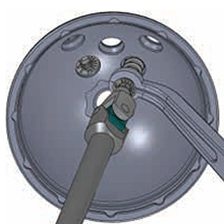
4
If using a Cluster or Multi-Hole cup,
bone screws may now be drilled for
and implanted. The screw(s) must be
fully seated to ensure engagement
of the Dual Mobility metal liner.
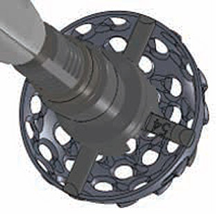
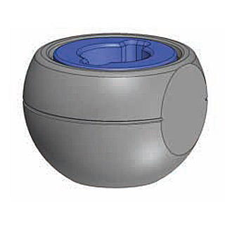
5
Gently introduce the dual mobility
metal liner into the cup and align
them by rotating the liner along the rim of the cup until the liner tabs drops
into the cup scallops. The liner is ready
to be impacted.
6
Impact the metal liner with
the impactor taper-lock, using
appropriate force. Ensure the metal
liner is fully seated without being
canted or tilted.
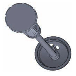
7
Assemble the corresponding femoral
head trial with the desired offset
on the femoral stem trunnion and
reduce the joint to assess stability,
leg length, joint tension, and range
of motion. Adjust offset if necessary
and remove trial components once
satisfied.
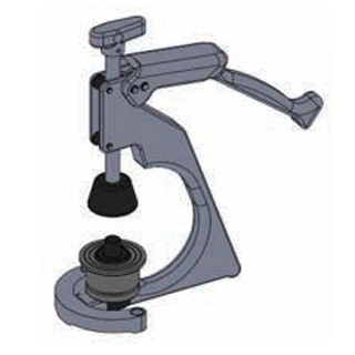
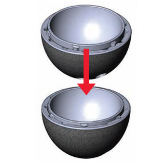
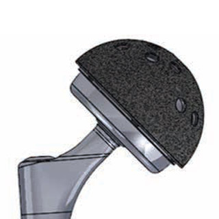
8
Perform back-table assembly of the
corresponding polyethylene bearing
and 28mm inner femoral head. Using
the assembly fixture, feel the initial
big “drop” for initial capture and then a
smaller “slip” to finish assembly. The
inner head must be able to articulate
freely inside the polyethylene bearing.
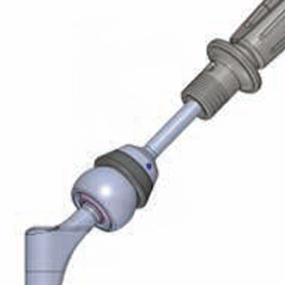
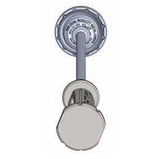
9
Place the assembled implants on the
femoral stem trunnion and impact
with the head pusher to taperlock.
Ensure the head-neck taper
connection is secure.
10
Perform final reduction of the joint
and assess stability, leg length, joint
tension and range of motion.

- Compared to Biomet G7, Stryker MDM, SNN OR3O, whose head sizes are available in their respective Surgical Techniques
- Padgett Et al. Orthopaedic Proceedings Vol. 101-B, No. SUPP_12, The British Editorial Society of Bone & Joint Surgery, Oct 2019
- e+™ testing data on file. Bench test results not necessarily indicative of clinical performance
Data on file at DJO Global® - P.F. Lachiewicz Orthopaedic Proceedings Vol. 100-B, No. SUPP_10, The British Editorial Society of Bone & Joint Surgery, Jun 2018